Technical information

Design of a membrane keypad
As a rule, the outward-facing side of the transparent membrane is matt. Printing of the front membrane takes place on the back. This protects the printing against environmental influences such as dirt, moisture and scratches. Front membrane, switch membrane, distance membranes and base membrane are glued together using high-quality adhesive membranes. If required, they can then be pressed together. Pressing of the membrane keypad is not standard, and is only carried out for special requirements, e.g. for increased tightness or impermeability to alcohol.
Conductive silver
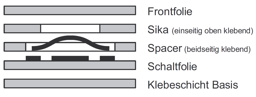
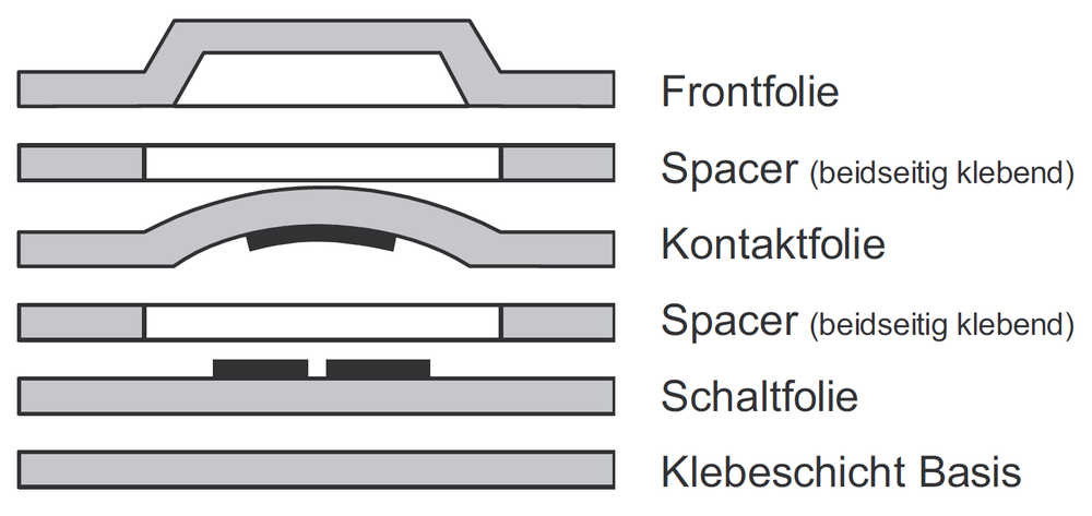
Version 1 (standard)
Membrane keypad with tactile action point
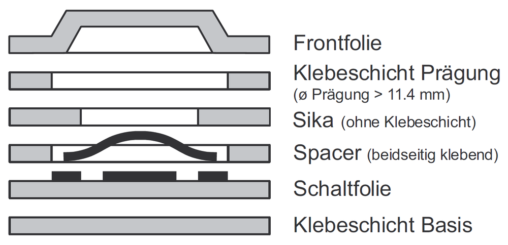
Version 2
Membrane keypad with tactile action point and embossing
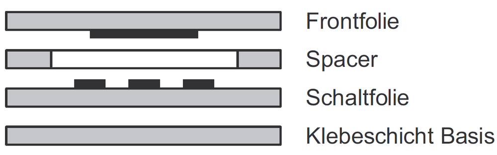
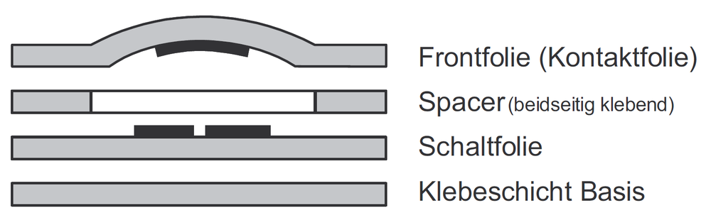
Version 3
Membrane keypad without tactile action point
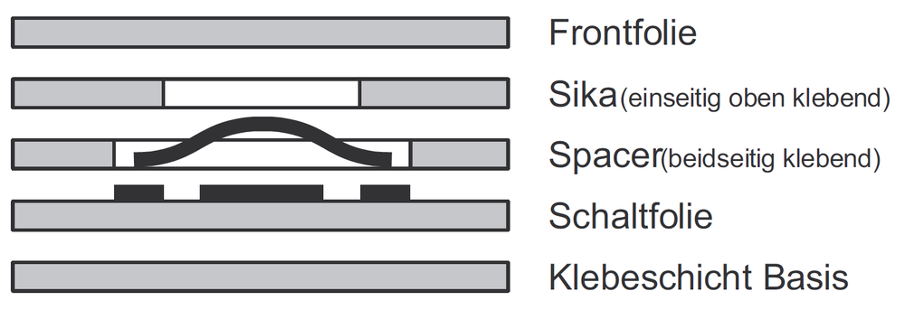
Version 4
Membrane keypad with tactile action point and embossing (Mylardom indirect)
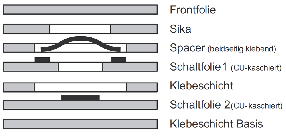
Version 5
Membrane keypad with tactile action point and embossing (Mylardom direct)

Display glass
In addition to closed, crystal-clear membranes (front membrane), glass is very frequently used for a window. The following materials are available:
■ Acrylic glass (e.g. Plexiglass)
■ (Polycarbonate (e.g. Macrolon))
■ Mineral or float glass

Flexible flat cables
The position of the exit point and the related length of the connection membrane should be specified during the design phase. The connection contacts are led out via the tail. The connecting lug is punched out of the keypad in the area of the exit so that the membrane cannot tear when bent. The standard grid is 1.0 mm. Avoid frequent bending. The ideal bending radius for the cable is > 4 mm.

LEDs
In addition, LEDs, brightness sensors, resistors or diodes can be integrated in the keypad (dependent on the height). For this purpose, the front membrane must be provided with cap embossing if necessary in the area of the LEDs.

Assembly
BOPLA offers a complete service Processing and assembly services. The customer benefits from faster delivery times, ordering expenses and a reduced risk of rejects. In this way, the matching of the keyboard adhesive layer to the various enclosure surfaces and accuracy of fit can be guaranteed.


Connector
The tail (flexbile flat cable) can either be led to a FFC direct plug soldered onto the PCB, or a female connector is crimped onto the tail (grid: 2.54 mm). If female connectors are crimped on, a single-row male connector must be provided as a counter-piece from the PCB.

External contour
Pay attention to the degree of tolerance when planning a membrane keypad/front membrane on a supporting plate or in the enclosure. The shape can be designed as required in accordance with the requirements of the specific application. The standard tolerance for a keypad or membrane surface is +/-0.3 mm.

Insertion pockets
Insertion pockets can be incorporated in the keypad for individual subsequent marking of keys or surfaces. Exchangeable insertion strips (e.g. for logos) can be fitted from the side, front or the rear. The insertion pocket is directly behind the front membrane, so the insertion strip is visible in the unprinted area.

Colours
For printing front membranes, special screen printing colours, so-called push button colours, are used for plastics. Printing takes place on the rear, so the layers of paint are protected against environmental influences. Standard colours are selected and used according to RAL. Colours can also be printed according to HKS and the Pantone scale. Additives for special colours are invoiced at cost. For special colours (e.g. a company’s colours), sample colour charts should be made available for the mixing procedures for the colours.
More information on screen printing

Front membrane design
When designing the layout of the front membrane, maintain a minimum line thickness of 0.3 mm. Line thicknesses of less than 0.3 mm do not guarantee high print quality. Corel DRAW files including *.cdr, *.eps,*.ai, *.ps, *.DxF can be provided for the front membrane design. It is important to use vectorised data.

Embossing
The main reason for embossing the membranes is to improve operation. Areas of the keys can be felt, and the membrane effect of the embossing improves the tactile response from the operating elements. Of course, embossing can also feature as a design element which highlights design membrane areas.

Dome embossing
Dome or bubble embossing is possible in diameters ranging from 8 to 17 mm.
*May diverge, depending on membrane material.

Raised embossing
Raised embossing can be executed in various forms.
*May diverge, depending on membrane material.

Profiline embossing
This especially high embossing forms the basis of our Profiline keypads.
*May diverge, depending on membrane material.

Rim embossing
Rim embossing is applied as a guide for the fingers. The surface level of the front membrane and key surface remain the same.
*May diverge, depending on membrane material.

Cap embossing
Cap embossing is a cap-shaped projection. This form of embossing is used for installation of LEDs, enabling levelling out of component height and intensification of the illumination effect.
*May diverge, depending on membrane material.
Protection classes
When laminating the keypad onto a carrier, we recommend using a suitable adhesive on the cable output. If the keypad is pressed onto the carriers by means of a pressing device, the keypad is absolutely watertight (also impermeable to alcohol, depending on the design). If an enclosure, in connection with a keypad, is to achieve protection class IP65, note the following:
■ The cable bushing into the enclosure must be sealed with a special adhesive.
■ It may be necessary to adapt the construction of the keypad.


Circuits
a) Common control line
Each key is connected to the common conductor and a printed conductor output. Additional decoding is not necessary. All leads are led to a highly flexible flat cable (FFC) in order to connect the entire keypad to the electronics.
b) X-Y matrix
The horizontal X output conductors and the vertical Y output conductors are connected to the contact points of the keys. This allows the connections to be reduced to just a few conductors.
| Copper technology with snap domes | CU/LS technology with snap domes | Keypad on PCB | |
|---|---|---|---|
| Protection class to the front (dependent on design) | up to IP67 | up to IP67 | up to IP67 |
| Snap domes gold-plated on the contact side | from 5 mm up to 10 mm | from 5 mm up to 10 mm | from 5 mm up to 10 mm |
| Key area | from 5 x 5 mm | from 5 x 5 mm | from 5 x 5 mm |
| smallest centre clearance of the keys | between 8 mm and 13 mm | between 8 mm and 13 mm | between 8 mm and 13 mm |
| typical height | from approx. 0.6 mm to approx. 0.9 mm | from approx. 0.6 mm to approx. 0.9 mm | from approx. 0.7 mm to approx. 3.8 mm |
| Switch travel (dependent on embossing) | approx. 0.3 to 0.65 mm | approx. 0.3 to 0.65 mm | approx. 0.3 to 0.65 mm |
| Switching force dependent on membrane | between 3 N and 5 N | between 3 N and 5 N | between 3 N and 5 N |
| Operating life (dependent on snap dome used) | from 300,000 to >1 mio. test processes acc. to DIN 42115 | from 300,000 to >1 mio. test processes acc. to DIN 42115 | from 300,000 to >1 mio. test processes acc. to DIN 42115 |
Electrical data:
| Current | max. 100 mA | max. 100 mA | max. 100 mA |
| Voltage | max. 35 VDC | max. 35 VDC | max. 35 VDC |
| Maximum output | 0.6 W | 0.6 W | 0.6 W |
| Conductor resistance (at 100 mm length and 1 mm width)* | <0.1 Ohm | <0.1 Ohm | <0.1 Ohm |
| Isolation resistance | >100 MOhm | >100 MOhm | >100 MOhm |
| Bouncing time (dependent on actuation) | <10msec | <10msec | <10msec |
Operating temperature:
| Keypads with embossing** | -20 °C to 70 °C | -20 °C to 70 °C | -20 °C to 70 °C |
| Keypads without embossing | -20 °C to 70 °C | -20 °C to 70 °C | -20 °C to 70 °C |
Storage temperature:
| Keypads with embossing** | -30 °C to 80 °C | -30 °C to 80 °C | -30 °C to 80 °C |
| Keypads without embossing | -40 °C to 80 °C | -40 °C to 80 °C | -40 °C to 80 °C |
*The resistance of the conductors depends on the layout design. Conductive silver bridges can increase the conductor resistance.
**The embossing may regress slightly in the higher temperature range.
Requirements with differing data on request.
| Conductive silver technology with snap domes | Mylardom with direct contact on conductive silver base | Mylardom with indirect contact on conductive silver base | |
|---|---|---|---|
| Protection class to the front (dependent on design) | up to IP67 | up to IP67 | up to IP67 |
| Snap domes gold-plated on the contact side | from 7 mm up to 10 mm | ø7mm/ø8mm/ø9mm/ø10mm | ø7mm/ø8mm/ø9mm/ø10mm |
| Key area | from 7 x 7 mm | ||
| smallest centre clearance of the keys | between 10 mm and 13 mm | between 10 mm and 13 mm | between 10 mm and 13 mm |
| Height | from approx. 0.6 mm to approx. 0.9 mm | approx. 0.6 mm | 1 mm |
| Switch travel (dependent on embossing) | approx. 0.3 to 0.65 mm | approx. 0.3 to 0.6 mm | approx. 0.3 to 0.65 mm |
| Switching force dependent on membrane | between 3 N and 4 N | between 2 N and 4 N | between 2 N and 4 N |
| Operating life (dependent on snap dome used) | >1 mio. test processes acc. to DIN 42115 | > 300,000 test processes acc. to DIN 42115 | > 500,000 test processes acc. to DIN 42115 |
Electrical data:
| Current | max. 100 mA | max. 100 mA | max. 100 mA |
| Voltage | max. 35 VDC | max. 35 VDC | max. 35 VDC |
| Maximum output | 0.6 W | 0.6 W | 0.6 W |
| typical conductor resistance (at 100 mm length and 1 mm width) | <10 Ohm | <10 Ohm | <10 Ohm |
| Isolation resistance | >100 MOhm | >100 MOhm | >100 MOhm |
| Bouncing time (dependent on actuation) | <10msec | <10msec | <10msec |
Operating temperature:
| Keypads with embossing** | -20 °C to 70 °C | 0 °C to 45 °C | 0 °C to 45 °C |
| Keypads without embossing | -20 °C to 70 °C |
Storage temperature:
| Keypads with embossing** | -30 °C to 80 °C | -30 °C to 45 °C | -30 °C to 45 °C |
| Keypads without embossing | -40 °C to 80 °C |
**The embossing may regress slightly in the higher temperature range.
Requirements with differing data on request.
| Profiline B | Profiline XE | |
|---|---|---|
| Protection class to the front (dependent on design) | up to IP67 | up to IP67 |
| front membrane material used | Bayfol CR 6-2 | Autotex XE |
| Snap domes gold-plated on the contact side | 8 mm and 10 mm | 8 mm and 10 mm |
| Key area | from 5 x 5 mm up to approx. 30 x 30 mm | from 7 x 7 mm up to approx. 30 x 30 mm |
| smallest centre clearance of the keys | between 16 mm and 40 mm | between 16 mm and 40 mm |
| Minimum clearance key edge to key edge* | between 11 mm and 24 mm | between 11 mm and 24 mm |
| Height | from approx. 1.4 mm to approx. 1.6 mm | from approx. 1.4 mm to approx. 1.6 mm |
| Embossing height | selectable: 1 mm, 1.5 mm, 2 mm | up to 1.0 mm |
| Switch travel (dependent on embossing) | approx. 0.3 to 0.65 mm | 0.65 mm |
| Switching force | between 3 N and 5 N | >5 N |
| Operating life (dependent on snap dome used) | from 300,000 to 500,000 test processes acc. to DIN 42115 | >1 mio. test processes acc. to DIN 42115 |
Electrical data:
| Current | max. 100 mA | max. 100 mA |
| Voltage | max. 42 VDC | max. 42 VDC |
| Maximum output | 0.6 W | 0.6 W |
| Conductor resistance (at 100 mm length and 1 mm width)** | <0.1 Ohm | <0.1 Ohm |
| Isolation resistance | >100 MOhm | >100 MOhm |
| Bouncing time (dependent on actuation) | <10msec | <10msec |
| Operating temperature | -20 °C to 45 °C | -20 °C to 70 °C |
| Storage temperature | -40 °C to 80 °C | -40 °C to 80 °C |
*These clearances depend on the inlay size
**The resistance of the conductors depends on the layout design. Conductive silver bridges can increase the conductor resistance. Requirements with differing data on request.
| Technology manufacturer | Analogue 4-wire | Analogue 5-wire |
| Protection classes: | ||
| Installation on front and rear without air vent | up to IP65 | up to IP65 |
| Installation on front and rear with air vent | up to IP64 | up to IP64 |
| full-surface laminated touch* | up to IP67 | up to IP67 |
| Actuation force | <50 g | <50 g |
| Light transmission: installation on front and rear | >80 % | >80 % |
| Light transmission full-surface laminated | >72 % | >72 % |
| Operating life | >1 mio. | >1 mio. |
| Electrical data: | ||
| Voltage | DC 5 V | DC 5 V |
| Isolation resistance | >10 MOhm at 25 V * | >10 MOhm at 25 V * |
| Current | 35 mA | 35 mA |
| Operating temperature | -10 °C to 60 °C | -10 °C to 60 °C |
| Storage temperature | -20 °C to 70 °C | -20 °C to 70 °C |
These data are based on the values of touch screens used in the past (resistive). Other touch types and manufacturers on request. Critical values should always be reconciled with the relevant data sheet.
*In the case of full-surface lamination, the minimum thickness of the touch unit material depends on the size of the sensor area. The larger this sensor area (diagonal) is, the thicker the sensor carrier glass should be (danger of breakage). Touch panels for systems with differing specifications on request.
| Characteristics | Polycarbonate PC | Polyester PETP | ||
|---|---|---|---|---|
| Mechanical characteristics | Tensile strength and stretch resistance: | good | Tensile strength and stretch resistance: | good |
| Scratch-proofing: | very good | Scratch-proofing: | very good | |
| Embossing and stamping processing: | very good | Embossing and stamping processing: | very good | |
| Printing: | very good | Printing: | very good | |
| Electrical characteristics | Dielectric strength: | Ø 60 kV/mm | Dielectric strength: | Ø 250 kV/mm |
| Isolation resistance: | 109 - 1011 Ω | Isolation resistance: | 109 - 1011 Ω | |
| Thermal characteristics | Temperature range: | - 50 ° to 120 °C | Temperature range: | - 70 °C to 150 °C |
| Melting point: | 220 °C | Melting point: | 250 °C | |
| Flammability: | slow to self-extinguishing | Flammability: | slow to self-extinguishing | |
| Optical characteristics | Light transmission, well-suited for LED displays. Colour reproduction slightly damped. | Very good light transmission, resulting in good visibility for LED and LCD displays. Good colour reproduction. | ||
| Chemical characteristics | Polycarbonate is resistant to mineral acids, many organic acids, oxidation and reduction agents, and acid salt solutions, many oils, saturated aliphatic cycloaliphatic hydrocarbons and alcohols, excluding methyl alcohol. | Polyester membrane is highly insensitive to moisture and most chemicals. Polyester is resistant against detergents, water, petrol, many oils, alcohol, vinegar, aliphatic hydrocarbons, bleaching agents, 2% ferric chloride solution, iodine, ethyl acetate, food dyes, machine oil; less resistant to chlorinated hydrocarbons, ketones, aromatic hydrocarbons. |
If different media are in contact with each other, the resistances may change. For this reason we cannot assume any liability for the information provided.


